
LIR2032 Charging at 4.20V: Error Budget and Termination
A higher voltage reading is not a better charger
Archived feedback for a historical clip-charger and LIR2032 bundle includes praise for simple operation. Other buyers interpreted a high voltage reading as evidence of quality. These are useful clues for product education, not calibrated measurements or proof of safety. OEM buyers need a defined measurement point, operating conditions and an approved cell specification.
VSZAPOWER's clip-charger demonstration shows red/blue indicators and battery placement. The associated new-version manual lists 4.2 V ±0.1 V output; it does not establish ±0.05 V regulation at the battery terminals. Its blue indication also covers an empty holder. A narrower accuracy claim therefore requires version-specific verification, independently of whether operation feels convenient.
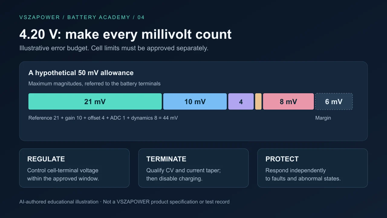
The cover is an original educational error-budget illustration, not a product circuit or test result.
First define what 4.20 V means
EEMB's reference LIR2032 is rated 3.7 V and 45 mAh. Its standard charge procedure at 25°C uses 0.2C constant current to 4.20 V, then constant voltage until current falls below 0.05C. Accordingly, I_CC = 0.2 × 45 mAh / 1 h = 9 mA, while I_TERM = 2.25 mA. These values describe that manufacturer's cell and procedure. EEMB datasheet, sections 2 and 5.1.
The cited procedure does not grant a universal 4.25 V ceiling. Writing “4.20 V ±0.05 V” creates a 4.15–4.25 V acceptance interval; the cell supplier must explicitly approve its upper endpoint. If the approved maximum is 4.20 V, a controller centered there with positive error has insufficient margin.
⚠ WARNING: Reaching 4.20 V begins the reference CV stage; it does not establish instant full charge. Voltage regulation, current-based termination and fault protection are separate requirements. Do not continuously trickle-charge lithium-ion cells. ML2032 needs its own approved charging profile; primary CR cells must never be charged.
Allocate error before selecting components
At 4.20 V, 50 mV / 4,200 mV × 100 = 1.19%. That allowance must cover the complete regulated output, not just an ADC's resolution.
The following is a hypothetical custom MCU voltage-loop budget. All entries are battery-referred maximum magnitudes across the intended conditions, not measured VSZAPOWER specifications.
| Contribution | Illustrative allowance | Qualification focus |
|---|---|---|
| Reference, including drift | 21 mV | Temperature and aging |
| Divider and gain error | 10 mV | Ratio tolerance and drift |
| Residual offset | 4 mV | Calibration limits |
| Quantization contribution | 1 mV | Battery-referred ADC step |
| Regulation ripple and overshoot | 8 mV | Input and load transitions |
| Worst-case sum | 44 mV | 6 mV remains within a 50 mV target |
Add bounded errors arithmetically for this worst-case check. A smaller statistical estimate needs justified distributions and dependencies. Do not add component errors again if an IC's guaranteed overall accuracy already includes them.
For comparison, TI specifies BQ25170 voltage accuracy of ±0.5% at 25°C and ±0.8% across its stated junction-temperature range: ±21 mV and ±33.6 mV at 4.20 V. The IC temperature range is not a permissible cell-charging temperature range. This example illustrates specification reading, not a recommendation that this IC automatically matches the EEMB profile. TI BQ25170 datasheet, section 6.5.
Measure the cell, not just the controller
Assume 30 mA passes through a hypothetical 2 Ω combined lead/contact resistance. The drop is I × R = 60 mV. At 2.25 mA it becomes 4.5 mV. If the controller senses before that resistance, the cell sees less voltage while charging; simply raising the setpoint to compensate at high current can overcompensate as current tapers.
Use separate sense connections at the intended measurement point where practical. Include fixture resistance and calibrated instrument uncertainty in acceptance testing. Under a conservative ±6 mV measurement-error assumption, a hypothetical 4.20 V upper limit requires measured voltage + 0.006 V ≤ 4.20 V. This is a test guard band, not a universal charging setpoint.
Qualify completion separately
A low current caused by input starvation or thermal limiting is not necessarily charge completion. TI's BQ25170 qualifies termination using voltage and current conditions, inhibits termination during thermal regulation, and disables its regulator after completion. Its termination setting is device-specific. TI datasheet, section 7.3.2.
For an MCU-supervised design, log cell voltage, cell current, temperature and state together. Check startup, near-completion behavior and removal/reinsertion. Account separately for a powered system's current; our CC/CV guide explains why it can conceal the battery's taper. Validate both normal regulation and independent fault response.
Price the verification work
Consider an illustrative 2,000-unit OEM order. Assume improved verification costs $0.20 per unit plus $250 setup. If voltage-related support interventions hypothetically fall from 3% to 1%, at $20 per intervention:
- Added cost = 2,000 × $0.20 + $250 = $650.
- Avoided support cost = 2,000 × (0.03 − 0.01) × $20 = $800.
- Net saving = $150; incremental ROI = $150 / $650 = 23.1%.
These are assumptions, not failure rates derived from archived reviews. At the same per-unit assumptions, break-even volume is $250 / ($0.40 − $0.20) = 1,250 units. Common product and operating costs cancel; any additional equipment, scrap or labor must be added.
For a procurement review, contact VSZAPOWER with the exact cell revision, approved voltage window and test conditions. Agree on measurable acceptance criteria before adopting a tighter accuracy claim.
Explore VSZAPOWER battery and charger solutions
Compatibility depends on the charger configuration and battery charging requirements. Confirm the supported battery model before use.
Inquire Wholesale Quote (Contact for Wholesale Quote)