
LIR2032 CC/CV Charging Curve: Current, Time and Termination
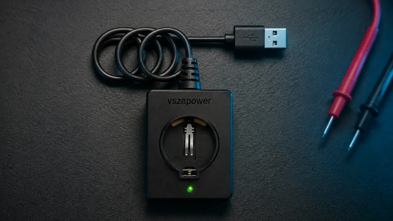
AI-styled scene based on original VSZAPOWER product imagery
The voltage plateau is a charging stage
For an IoT integrator or battery-service operator, “reached 4.20 V” and “finished charging” describe different events. The first can mark the transition from constant current (CC) to constant voltage (CV). The second requires the specified termination conditions. Confusing them creates unreliable runtime estimates, misleading charger-throughput claims and inconsistent acceptance tests.
Establish a model-specific reference
EEMB's currently linked LIR2032 specification, dated April 2019, describes a 45 mAh, 3.7 V cell. At 25°C, its standard procedure uses 0.2C charging; its fast procedure uses 1C. Both transition at 4.20 V and terminate below 0.05C. Converting capacity to current gives 9 mA, 45 mA and 2.25 mA respectively. These are that manufacturer's test conditions, not universal LIR2032 settings. EEMB datasheet, sections 2 and 5.1.
| Feature | Constant-current stage | Constant-voltage stage |
|---|---|---|
| Controlled quantity | Cell charging current | Cell terminal voltage |
| Reference standard procedure | 9 mA while voltage rises | 4.20 V while current tapers |
| Reference fast procedure | 45 mA while voltage rises | 4.20 V while current tapers |
| Exit condition | Reach the approved CV target | Current below 2.25 mA in this reference |
| Useful measurement | Current stability and voltage rise | Taper duration and actual battery current |
Read the curve as an electrochemical response
Terminal voltage includes the cell's equilibrium voltage plus current-dependent impedance and polarization contributions. Consequently, reaching the voltage ceiling under load does not by itself establish stored charge. As charging proceeds at the regulated ceiling, current must decrease. The cell is still accepting charge during that taper.
Analog Devices describes an exponential approximation for the CV current decline and explains why increasing initial current does not proportionally shorten the complete cycle. Cell and connection resistance matter. An aged cell or resistive holder can reach the ceiling earlier; a longer or altered taper warrants investigation rather than an automatic “full” label. Analog Devices charging discussion.
Integrate current instead of multiplying peak current by time
Consider an explicitly hypothetical curve: 45 mA CC for 42 minutes, followed by a CV taper I(t) = 45 mA × exp(−t/18 min). The time constant and CC duration are assumptions, not values measured from EEMB's graphs.
t_CV = 18 min × ln(45 mA / 2.25 mA) = 53.9 min
The modeled current reaches 2.25 mA after approximately 95.9 minutes total; strict “below threshold” termination occurs just after that crossing, subject to controller qualification.
Q_CC = 45 mA × 0.70 h = 31.5 mAh
Q_CV = 0.30 h × (45 − 2.25) mA = 12.825 mAh
Total input charge is therefore 44.325 mAh. This integral is not a guaranteed recoverable discharge capacity: initial state of charge, losses, temperature, aging and the discharge endpoint still matter. Replacing the curve with 45 mAh / 45 mA = 1 hour loses the taper information.
Terminate the battery current, not the whole device load
An operating BLE node may draw current while charging. If the charger measures the combined output, then I_sensed = I_battery + I_system. With an illustrative 3 mA system load and 1 mA entering the cell, the sensed 4 mA remains above the reference 2.25 mA threshold. The battery can be near completion while normal termination never occurs.
TI documents this problem in directly connected charger/system architectures, including longer charging and unwanted restart behavior. Use a qualified power-path arrangement or a measurement point that distinguishes cell current from system consumption. This architectural lesson does not make the cited higher-current ICs suitable for a coin cell without checking their ranges and resolution. TI SLUA376, sections 2–3.
⚠ WARNING: Do not defeat termination or extend the safety timer indefinitely to hide a stalled taper. Do not continuously trickle-charge a full lithium-ion cell. CV regulation, current termination and overvoltage protection are separate functions. A proposed 4.20 V ±0.05 V tolerance does not authorize 4.25 V on a cell specified for a lower maximum. Never apply this profile to CR cells or assume it suits ML2032.
Current-based completion and a maximum charging duration serve different purposes; both require appropriate design. Analog Devices termination guidance.
Translate taper duration into an operating-cost model
Assume a service team must recharge 60 existing cells daily during an eight-hour shift. Use the hypothetical 95.9-minute cycle above, four independent slots per dock and six minutes of handling per four-cell batch. Charging is unattended. Each dock then supports:
4 slots × floor(480 min / (95.9 + 6) min) = 16 charges/day
The team needs four docks. Assuming a 30-minute cycle instead would suggest 52 charges per dock daily and only two docks, understating required capacity.
For a 20-day month, assume $25 per dock, labor at $15/hour and a $1 allowance for charging plus standby electricity. These are budgeting assumptions, not VSZAPOWER quotations or measured consumption. Fifteen batches daily require 1.5 labor-hours. Charging-operation TCO, expensing the docks in month one, becomes:
TCO = 4 × $25 + 20 × 1.5 h × $15/h + $1 = $551
That is approximately $0.459 per completed charge across 1,200 charges. Cell purchases and qualification costs fall outside this operating example. Aged-cell cycle times, downtime and staffing conflicts require additional allowances; measure them before promising throughput.
Request evidence for the complete cycle
Ask for timestamped cell voltage, battery current, temperature and charger-state records from several representative cells, including aged samples. Specify starting charge level, holder resistance, supply conditions and the termination rule.
Review the LIR/ML/CR chemistry comparison, then use the charger manufacturing guide and B2B inquiry form to request a configuration matched to your cell and duty cycle.
Explore VSZAPOWER battery and charger solutions
Compatibility depends on the charger configuration and battery charging requirements. Confirm the supported battery model before use.
Inquire Wholesale Quote (Contact for Wholesale Quote)