
LIR2032 at 20–50mA: C-Rate, Precharge and Trickle Explained
Small current is relative to the cell
An OEM brief describing “20–50 mA microcurrent trickle charging” combines three different ideas: current magnitude, capacity-normalized rate and charging stage. Twenty milliamperes equals 20,000 microamperes. It may be modest for a large battery yet substantial for a rechargeable coin cell.
Archived buyers of a historical clip-charger and LIR2032 bundle praise straightforward operation and the opportunity to buy fewer replacement batteries. Other feedback reports short runtime despite apparently successful charging. These observations motivate clearer specifications; they do not establish charging current, lifetime savings or the cause of an individual problem.
VSZAPOWER's USB clip-charger demonstration shows the plug, battery placement and indicators. The new-version manual labels its USB input 5 V / 1 A. That input marking does not mean the battery receives 1 A. Nor does the owner's nominal 30 mA charger information establish a measured current profile for every connected cell. Procurement records should identify input requirements and battery-terminal current separately.
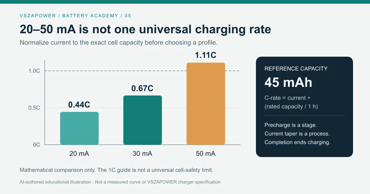
The cover is an educational C-rate comparison, not a measured charging curve or product performance claim.
Convert milliamperes into C-rate
Use the rated capacity of the exact approved cell revision:
C-rate = I_charge / (Q_rated / 1 h)
EEMB's reference LIR2032 is rated 45 mAh and 3.7 V. At 25°C its standard procedure specifies 0.2C CC charging to 4.20 V, then CV charging until current falls below 0.05C. The fast procedure specifies 1C, with the same voltage and termination fraction. EEMB datasheet, sections 2 and 5.1.
| Battery current | Rate for this 45 mAh reference | Interpretation |
|---|---|---|
| 9 mA | 0.20C | Reference standard CC procedure |
| 20 mA | 0.44C | Requires qualification for the chosen profile |
| 30 mA | 0.67C | Requires qualification for the chosen profile |
| 45 mA | 1.00C | Reference fast CC procedure at 25°C |
| 50 mA | 1.11C | Above the cited fast-procedure current |
Being between two documented test currents does not automatically approve an intermediate operating profile. Another supplier's LIR2032 may have different capacity and limits. For a hypothetical 20 mAh cell, the same 30 mA becomes 1.50C; that arithmetic grants no charging approval.
Include current-setting tolerance
Suppose an approved engineering ceiling is 45 mA and the complete positive current-setting error is bounded at 10%. The nominal setting must satisfy I_set × 1.10 ≤ 45 mA, giving I_set ≤ 40.9 mA. This is an illustrative tolerance calculation, not a new EEMB charging recommendation. Include programming-component tolerance and drift unless already covered by the complete error bound.
Precharge, taper and maintenance are different
Precharge addresses a supplier-approved low-voltage condition before normal CC charging. It requires defined entry and exit thresholds, temperature limits and a timeout. The standard EEMB procedure above does not establish a universal deeply discharged-cell recovery method.
TI's BQ25170 uses “trickle” for its lowest-voltage charging stage, not indefinite maintenance after full charge. Its nominal normal-charge range starts at 10 mA; precharge is typically 20% of the programmed current, while termination is typically 10%. At a 30 mA setting those are 6 mA and 3 mA, respectively. They are distinct functions, and 3 mA differs from the reference cell's 0.05C = 2.25 mA endpoint. TI BQ25170 datasheet, sections 6.5 and 7.3.2.
The same IC separately specifies 12–20 mA in its lowest-voltage short-circuit charging region. Consequently, selecting a low normal-charge current does not ensure every earlier stage supplies a smaller current. Review the entire profile before choosing an IC for a small cell.
During CV, current tapers as voltage is regulated. Termination then disables charging when qualified conditions hold; it is not a command to keep feeding a tiny maintenance current. Our CC/CV guide explains why reaching the voltage target alone does not mean full charge.
⚠ WARNING: Do not continuously trickle-charge lithium-ion coin cells after completion, or attempt to revive damaged cells. Follow the exact supplier's recovery policy. Never charge primary CR cells. ML2032 needs its own chemistry-specific voltage and current limits; lowering a fixed 4.2 V charger's current does not make it suitable for ML.
For example, Maxell specifies 2 mA or lower for its ML2032 and prohibits charging above 3.3 V. These are Maxell requirements, not verified VSZAPOWER settings. They demonstrate why “20–50 mA for all rechargeable coin cells” is unsuitable. Maxell ML guide, page 2.
Faster charging must improve the actual workflow
Consider an illustrative B2B service bench needing 120 equivalent recharges weekly, with 40 available hours per channel. Assume two qualified profiles deliver the same usable energy per recharge and comparable cell life. Total charge times, including CV, are hypothetically 2.0 and 1.5 hours; neither is derived simply from capacity divided by CC current.
- Baseline channels = ceil(120 × 2.0 / 40) = 6.
- Faster-profile channels = ceil(120 × 1.5 / 40) = 5.
- At an assumed $50 per channel, avoided equipment cost is $50.
- With $200 incremental qualification cost, net saving is −$150 and incremental ROI is −75%.
This idealized schedule excludes changeovers; unchanged electricity, labor and cell-replacement costs cancel only by assumption. Add their actual differences before deciding. Faster charging is not automatically cheaper, and an unsupported current increase is not an acceptable route to savings.
Contact VSZAPOWER with the exact cell, charger revision and workload. Request stage-specific current limits and qualified charge-time data before approving a bulk configuration.
Explore VSZAPOWER battery and charger solutions
Compatibility depends on the charger configuration and battery charging requirements. Confirm the supported battery model before use.
Inquire Wholesale Quote (Contact for Wholesale Quote)